Search
Materials and Coatings
Carbon Fiber-Carbon Nanotube Yarn Hybrid Reinforcement
NASA's new material is a toughened triaxial braid made from ductile carbon nanotube (CNT) yarn hybridized with carbon fiber, which is ultimately used as reinforcement material to make toughened polymer matrix composites. The CNT yarn component of the reinforcement is solely responsible for adding toughness, while the processes used to optimize the fiber braiding parameters and tensile properties of the carbon fiber-CNT yarn hybrid tow material determine the overall improvement in tensile strength for resin impregnated fiber tows. Bundles of continuous carbon nanotube yarns are combined with a similar format of carbon fiber, yielding an easily scalable process.
Advantages of the material include reduced cost by eliminating use of toughening agents, increased ability to conform to highly complex geometries, greater environmental stability compared to aramid fiber reinforcements such as Kevlar, and possibly decreased density. Many hybrid reinforcements exhibit interfacial compatibility issues, which could lead to premature failure via crack propagation at the polymer matrix interface. In contrast, chemical similarities between the CNT yarn and carbon fiber constituents impart NASA's hybrid reinforcement material with excellent interfacial compatibility.
Potential applications include aerospace components, composite pressure vessels, wind turbine blades, automotive components, prosthetics, sporting equipment, construction reinforcement material, and other use-cases where strength-to-weight ratio is of utmost importance.
materials and coatings
Origami-based Deployable Fiber Reinforced Composites
Deployable space structures often rely upon telescoping or folding structures that either must be manually deployed or deployed by attached motors. These structures are often made from heavier (relative to carbon fiber composites) metals to provide enough strength to support a load. As such, there is a need for in-space structures that are lightweight, can be packaged compactly, and can be deployed easily.
The composite material developed here does not require high temperature baking to cure the polymer, rather relying on UV light to solidify the polymer component. The composite is then included into origami-based structures that can fold and deploy using the polymer shape memory effect. The composite is first trained to assume the deployed structural shape when heated; it is then folded like origami and frozen into the packaged shape for storage and launch. Combining the composite material with the origami-inspired design leads to high strength structures (can hold at least 600 kg on Earth). To date, a ~5-inch prototype structural bar has been produced using the UV-curable composite and further development is on-going at NASA Langley.
The deployable origami composite structures are at technology readiness level (TRL) 4 (component and/or breadboard validation in laboratory environment) and are available for patent licensing.
materials and coatings
Conductive Carbon Fiber Polymer Composite
The new composite developed by NASA incorporates PGS and CNTs to enhance its thermal conductivity while preserving the mechanical properties of the underlying carbon fiber polymer composite. NASA has also improved the composite manufacturing process to ensure better thermal conductivity not only on the surface, but also through the thickness of the material. This was achieved by adding perforations that enable the additives to spread through the composite.
The process for developing this innovative, highly thermally conductive hybrid carbon fiber polymer composite involves several steps. Firstly, a CNT-doped polymer resin is prepared to improve the matrix's thermal conductivity, which is then infused into a carbon fiber fabric. Secondly, PGS is treated to enhance its mechanical interface with the composite. Thirdly, perforation is done on the pyrolytic graphite sheet to improve the thermal conductivity through the thickness of the material by allowing CNT-doped resin to flow and better interlaminar mechanical strength. Finally, the layup of PGS and CNT-CF polymer is optimized.
Initial testing of the composite has shown significant increases in thermal conductivity compared to typical carbon fiber composites, with a more than tenfold increase. The composite also has higher thermal conductivity than aluminum alloys, with more than twice the thermal conductivity of the Aluminum 6061 typically used in the aerospace industry. For this new material, NASA has completed a proof-of-concept demonstration and work continues to use the material in a heat exchanger system and further characterize the properties including longevity and radiation impact analysis.
Materials and Coatings

Vertically Aligned Carbon Nanotubes
Formation of the inventive polymer composite matrix begins by growing carbon nanotubes directly on a veil substrate. The carbon nanotubes are grown from both sides of a non woven carbon fiber mat. The carbon nanotubes can be single or multi walled and can be grown to predetermined lengths. The veiled substrate is positioned between carbon fiber/ polymer prepreg layers such that the carbon nanotubes protrude into the reinforcement layers. The polymer composite matrix formed following curing of the resin exhibits improved interlaminar strength, fracture toughness and impact resistance. Because of the thinness of the veil layer, electricity can pass from conductive carbon nanotubes on one side of the veil to conductive carbon nanotubes on the other side of the veil. Electricity can also pass between two veils intercalated into the same reinforcement layer when the length of the nanotubes is sufficiently long enough to provide overlap within the reinforcement layers.
manufacturing
Calibration System for Automated Fiber Placement
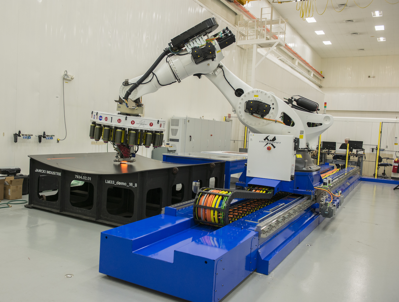
NASA's new calibration system is a proprietary method to quickly design and make predictable and repeatable gap-and-overlap defects when employing AFP. The system creates defects within the course of layup with known sizes, geometries, and locations. Using this defect-creation technique, one can now accurately quantify the ability to detect defects on inspection systems, perform accurate risk assessments, and calibrate in-situ inspection equipment to specific materials. The equipment that makes the defects can be efficiently and inexpensively 3D printed. This technique is currently being used to successfully calibrate NASA's in situ inspection system for their AFP equipment.
AFP is experiencing increasing adoption in aerospace, automotive, and other industries that leverage large-scale advanced composite components. NASA's new AFP calibration system could be very useful to companies that develop and manufacture AFP machines or AFP machine inspection equipment to improve the quality of their products in a provable manner. Furthermore, users of AFP machines may find value in the tool for creating their own calibration standards.
Materials and Coatings
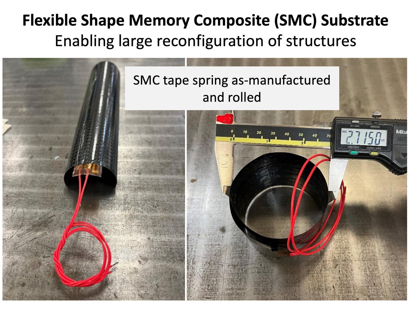
Novel Shape Memory Composite Substrate
The new SMC substrate has four components: a shape memory polymer separately developed at NASA Langley; a stack of thin-ply carbon fiber sheets; a custom heater and heat spreader between the SMC layers; and integrated sensors (temperature and strain). The shape memory polymer allows the as-fabricated substrate to be programmed into a temporary shape through applied force and internal heating. In the programmed shape, the deformed structure is in a frozen state remaining dormant without external constraints. Upon heating once more, the substrate will return slowly (several to tens of seconds) to the original shape (shown below).
The thin carbon fiber laminate and in situ heating solve three major pitfalls of shape memory polymers: low actuation forces, low stiffness and strength limiting use as structural components, and relatively poor heat transfer. The key benefit of the technology is enabling efficient actuation and control of the structure while being a structural component in the load path. Once the SMC substrate is heated and releases its frozen strain energy to return to its original shape, it cools down and rigidizes into a standard polymer composite part. Entire structures can be fabricated from the SMC or it can be a component in the system used for moving between stowed and deployed states (example on the right). These capabilities enable many uses for the technology in-space and terrestrially.
Power Generation and Storage

Carbon Fiber Sleeve Tempers Battery Thermal Runaway
The CFRP sleeve was originally intended for crewed space flight lithium-ion 18650 battery packs rated over 80 Watt-hours (Wh), which are required to be passively propagation-resistant for increased safety. Previous battery designs have addressed SWR propagation by using aluminum or steel interstitial materials to prevent SWRs from directly impacting neighboring cells, but these materials were underperforming.
During testing of 18650 battery cells, it was discovered that cells over 2.6Ah in capacity can have an undesirable failure mode in which the cell wall will rupture or breach during a thermal runaway (TR) event sending heat and ejecta into an undesirable direction. TR is typically triggered when heat produced by the battery cell’s exothermic reaction leads to increased and escalating internal cell temperature, pressure, and boiling of the electrolytes. When internal cell pressure exceeds the cell’s safety relief mechanism, rupture or bursting can occur, initiating a cell-to-cell propagation that in turn results in a battery pack fire.
By adding a carbon fiber reinforced polymer (CFRP) sleeve to cylindrical battery cells, a sidewall rupture (SWR) can be prevented from occurring or propagating. In initial testing, there were no SWRs of a battery cell using a CFRP sleeve. This result is believed to be due in part to a unique characteristic of CFRP sleeves compared to other materials. Carbon fiber material has a negative coefficient of expansion and accordingly shrinks when heated, while steel and aluminum expand. The shrinking of the CFRP sleeve when heated compresses the cell located within it, significantly aiding in the prevention of SWR.
This technology can be implemented into other multi-physics battery safety models to guide the design of the next generation of battery cells and battery packs.
This thermal runaway propagation resistant technology has a technology readiness level (TRL) of 6 (System/sub-system model or prototype demonstration in an operational environment) and is now available for patent licensing. Please note that NASA does not manufacture products itself for commercial sale.

